Transformer....
INTRODUCTION
In electrical engineering, Transformer plays a key role in the transmission and distribution of electric power. A transformer is a static electrical device, which does not having any moving parts. It transfers electric power from one circuit to another circuit without changing the frequency. The energy transfer usually takes place with a change of voltage and current. Transformers either increases or decreases AC voltage. It works between two circuits linked by a common magnetic flux on the principle of mutual induction. In other words, it consist of two inductive coils which are electrically separated but magnetically linked (i.e.) two windings are insulated from each other and wound on a common core made up of magnetic material, with less reluctance. If one coil is connected to a source of alternating voltage, an alternating flux is setup in the laminated that winding is called primary winding. The flux created in the core will cuts the secondary winding and primary as well. It produces mutually induced emf (according to Faraday's law). Transformers are used to meet a wide variety of needs. Some transformers can be several stories high, like the type found at a generating station or small enough to hold in your hand, which might be used with the charging cradle for a video camera. No matter what the shape or size, a transformers purpose remains the same: transforming electrical power from one type to another.
In brief, transformer is a device that:
1. Transfer electric power from one circuit to another.
2. It does so without a change of frequency.
3. It accomplishes this by electromagnetic induction.
4. The two circuits are in mutual inductive influence of each other.

Transformer Working Principle :
Add Your Heading Text Here
Here we are going to discuss that how a transformer works. Basically, a transformer functions under the law of energy conservation, which states that energy can neither be created nor destroyed, only transformed. Therefore, a transformer does not make electricity, it only changes the voltage as per required. Transformers accomplish this change in voltage through the process of electromagnetic induction.
What is Electromagnetic Induction :
First of all we should know that transformer only in AC power supply. It does not works in DC power system. When we run an AC supply through a wire (conductor), an invisible, moving magnetic field is created around the electrified conductor and if we place a second conductor within this changing magnetic field, the moving flux lines in the field induce a current in the second conductor.
We can use electromagnetic induction to increase or decrease voltage between the two conductors by wrapping the two conductors into coils with one being longer (having more turns in the coil), and the other shorter (having fewer turns in the coil). If we then electrify the coil having more turns, a current will be induced in the coil with fewer turns at a lower voltage than is present in the first coil. This is called Electromagnetic Induction, which is called Faraday's Law of Electromagnetic Induction.
Transformer Construction :
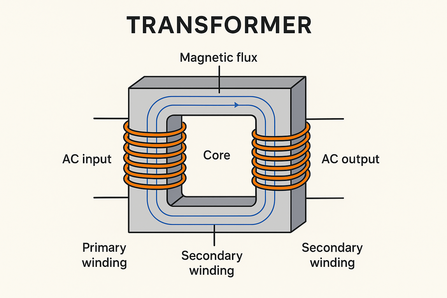
A transformer consists of three major parts namely a primary winding, a secondary winding and a magnetic core. The primary winding is one which is used to input the power supply and secondary winding is one that used to take output. The magnetic core is used to confine the magnetic flux to a definite path.
1. Windings :
There are two sets of windings as Primary winding and Secondary winding. They are made of copper (sometimes aluminum). Primary winding is connected to input supply and the Secondary winding connected to the output.
2. Core :
It acts as the heart of the transformer. It is made of laminated silicon steel to reduce eddy current losses. It provides a low reluctance path for magnetic flux.
3. Insulation :
It prevents short circuits between windings and between winding & core. Insulation materials are made of varnish, paper, epoxy, pressboard, etc.
4. Main Tank :
It's the main body where all parts are enclosed i.e. windings, cores and Oil. In oil-filled transformers, it contains insulating oil to provide both cooling and insulation to the windings and cores inside the transformer.
5. Conservator Tank :
It's a small auxiliary tank on top connected to the main tank through a pipeline to flow the oil. It provides space for oil expansion and contraction due to temperature rise inside the main tank. There is also a gauge glass to check the volume of the oil inside the conservator tank which is called MOG (Magnetic Oil Gauge). It is used to as protection part of the transformer. We discuss further about it later.
6. Breather :
Basically Breather is connected through a pipe line to the conservator Tank. When oil temperature is high due to increase the transformer load, cool air tends to move though this filter into the conservator tank, but there is used Silica Gel inside the filter to prevent the moisture which presents in the air which may affect the transformer oil or also windings. Filters air entering the conservator tank. Removes moisture using silica gel crystals.
7. Bushing :
Bushings are insulated devices that allow safe connection of external supply lines which connect to the transformer windings. Usually they are made of porcelain or epoxy resin.
8. Tap Changer :
Tap Changer is basically found in HT Transformers. It is used to regulate the output voltage as per requirement.
There are two types Tap Changer :
i) Off-load Tap Changer (adjustable only when transformer is OFF condition).
ii) On-load Tap Changer (can be adjusted while transformer is charged or in running condition).